Mechanical Infrastructure · Existing Conditions · Iterative Design
Pneumatic Air-Line Clamp
A tool-free support engineered to improve the routing and maintainability of compressed-air infrastructure without permanently modifying an operating production machine.
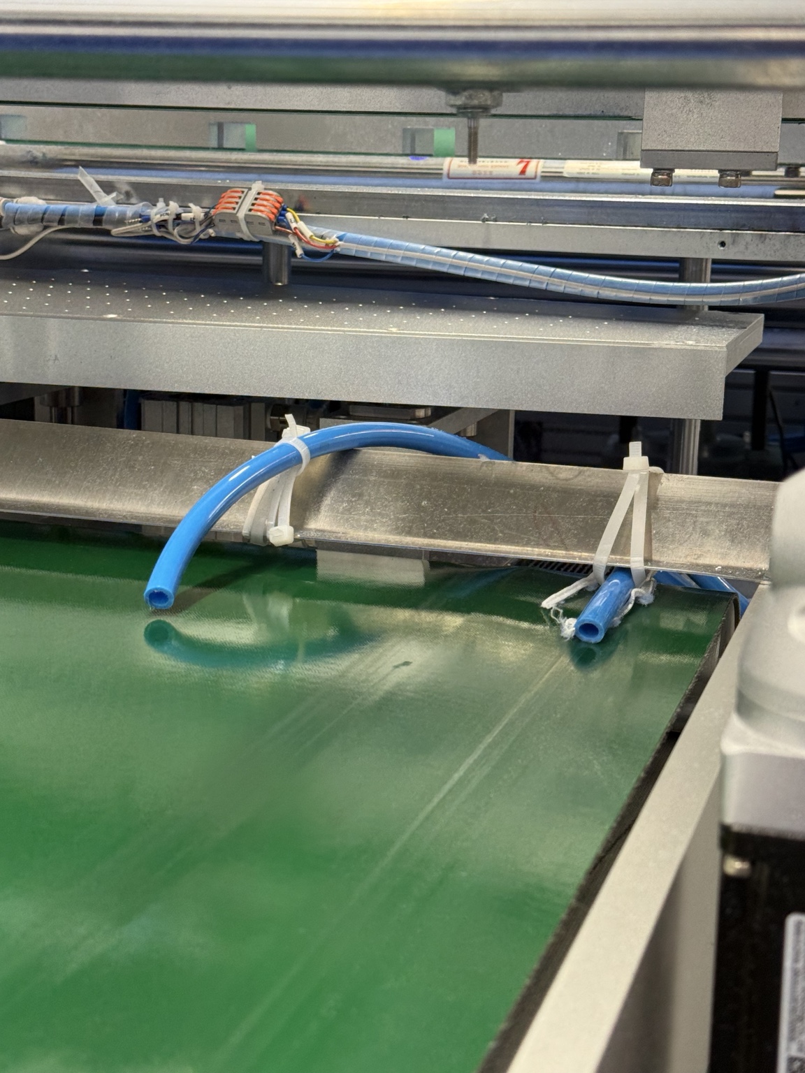
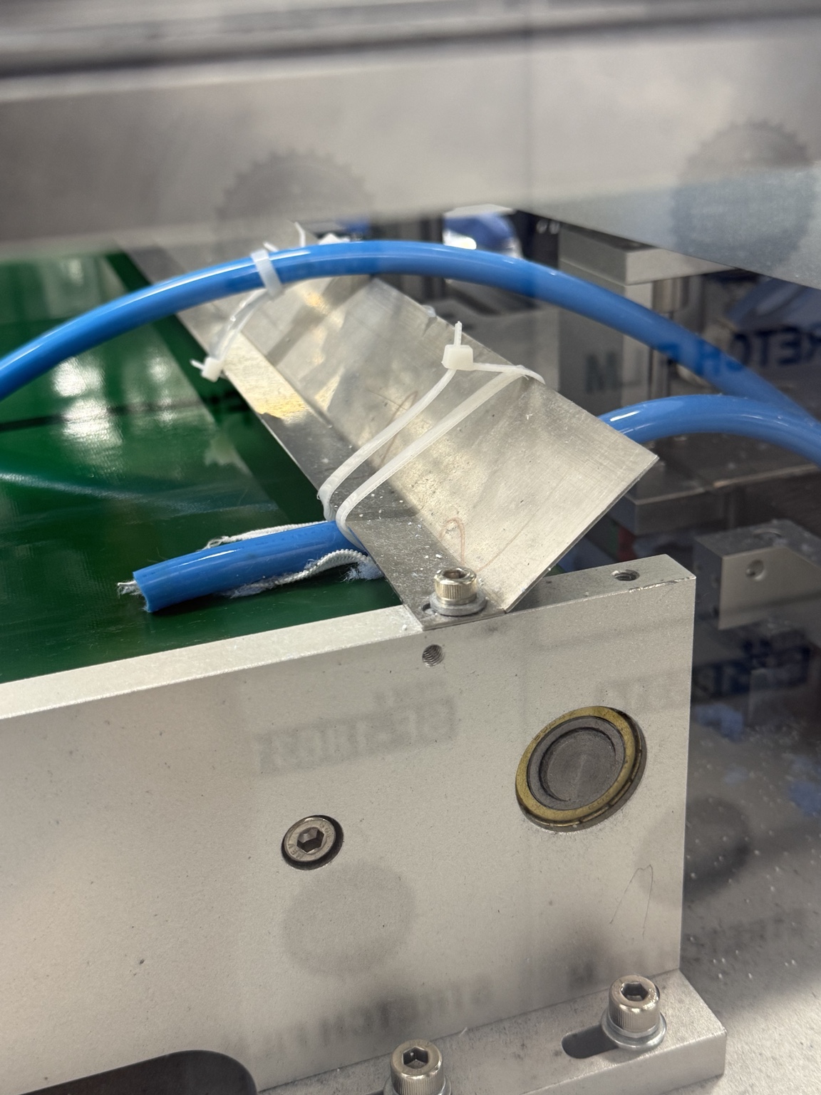
Before: Pneumatic air lines were held in place using zip ties and scrap fabric attached to the machine structure. The temporary setup allowed the tubing to shift and was difficult to standardize or maintain.
Site investigation and constraints
Secure the tubing without modifying the machine.
I evaluated the existing installation, tubing path, nearby moving equipment, available attachment surfaces, and maintenance access. The pneumatic lines needed a controlled route above the conveyor, while the temporary zip-tie arrangement could shift and could not be installed consistently across the system.
The machine offered no suitable mounting holes, ruling out screws and permanent modifications. The design also had to resist hose restoring force and machine vibration, grip a smooth low-friction surface, and remain easy to install, inspect, and replace.
- Company
- New York Embroidery Studio
- My role
- Mechanical Engineering Intern
- Methods
- Field measurement, constraint analysis, Fusion 360, 3D printing, on-machine testing
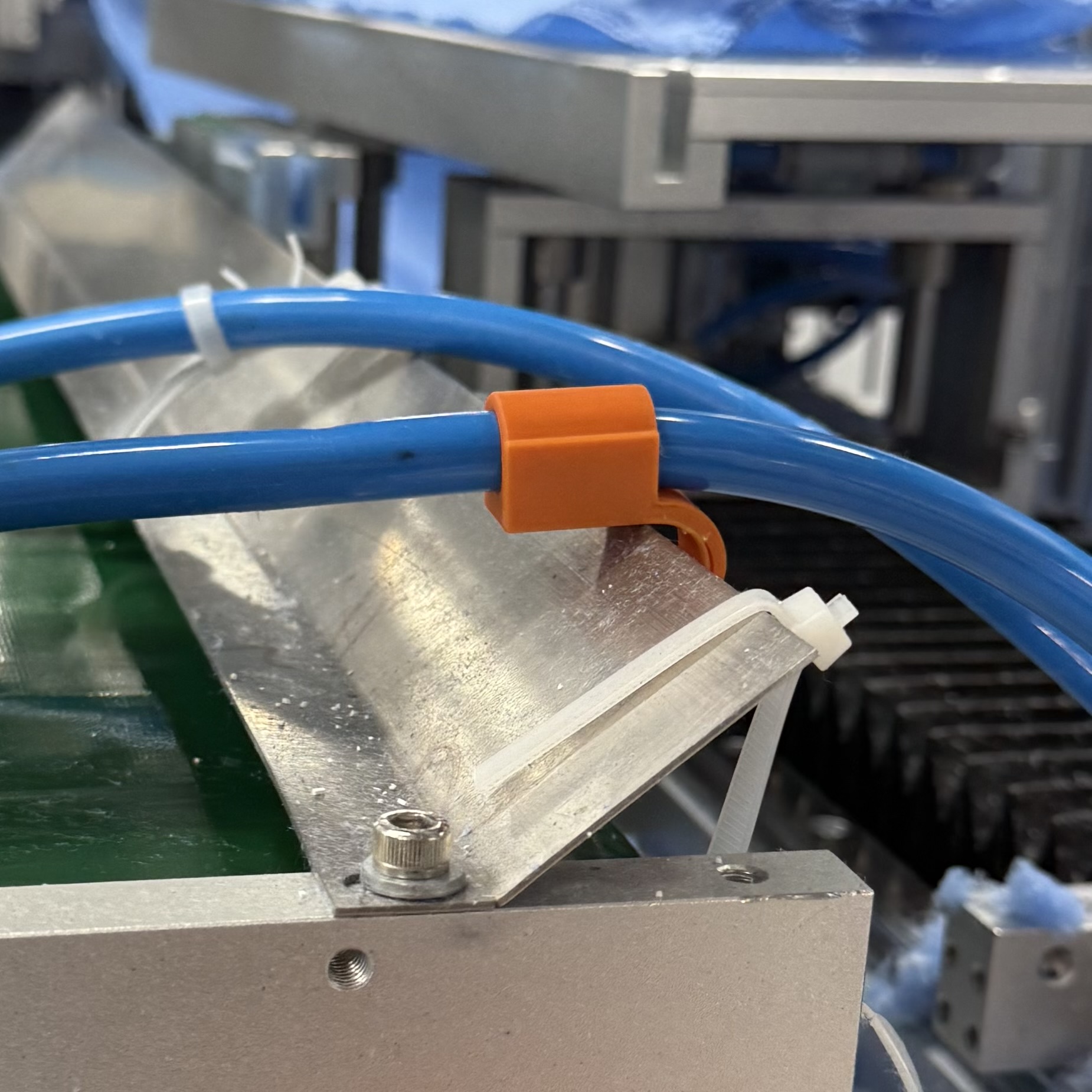
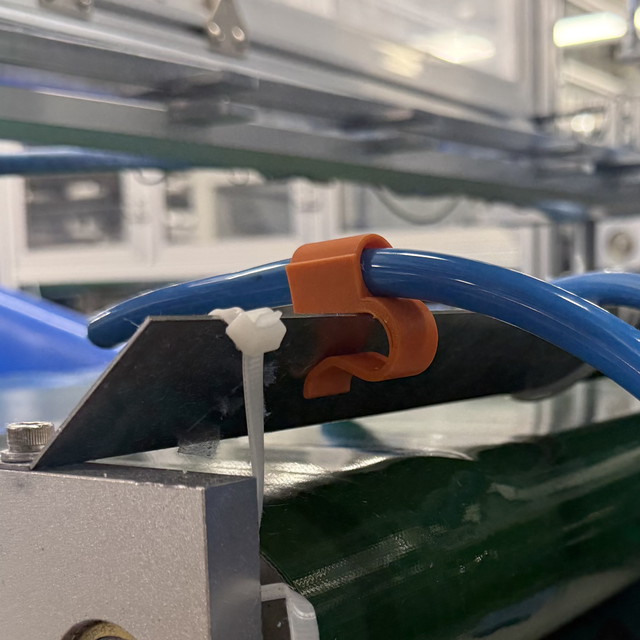
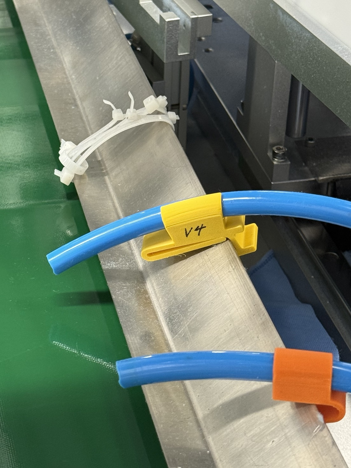
First iterations: The initial CAD design and 3D-printed clamp successfully captured the air line and attached to the machine edge, but on-machine testing revealed several mechanical challenges.
Iteration challenges
Using on-machine behavior to guide each redesign.
Hose force lifted the clamp. The pneumatic tube naturally wanted to return to its original curved position. That restoring force created an upward moment on the prototype, causing the mounting clip to lift away from the metal plate instead of remaining fully seated.
The mounting surface provided limited grip. The smooth, slightly greasy sheet metal produced very little friction. Even when the dimensions fit correctly, the clamp could slide along the edge rather than staying fixed in its intended position.
Machine vibration loosened the fit. Continuous vibration during operation gradually shifted the prototype and made a friction-only attachment less reliable over time.
Installation and retention had to be balanced. The tube could only be inserted from above because its surrounding geometry prevented it from sliding into the clamp from the side. The opening therefore needed enough flexibility for installation while still being tight enough to prevent the tube from escaping or rotating during operation.
I used these observations to refine the clamp's grip, alignment, barrel length, and internal contact features. The process showed that the final design had to account not only for static measurements, but also for tube stiffness, load direction, vibration, surface condition, and installation access.
Final iteration
A more secure geometry developed from real machine testing.
The final iteration incorporated the lessons from the early prototypes to improve retention, reduce movement, and better resist the direction of force applied by the pneumatic tube.
Design solution
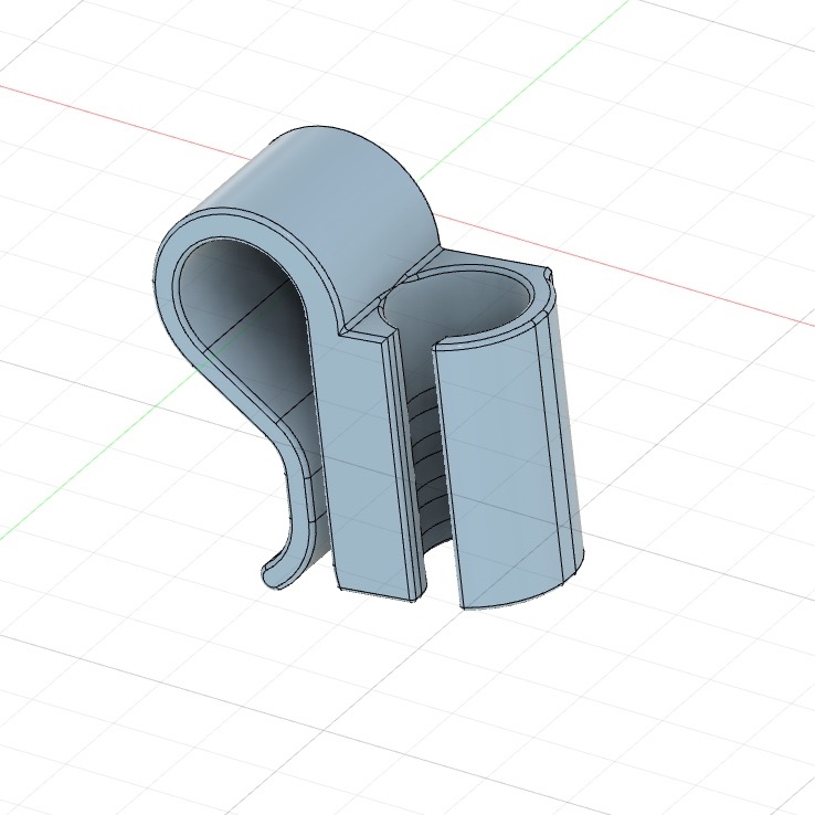
I developed a compact clip-on clamp with a curved barrel sized to capture the pneumatic tube and a mounting feature designed to grip the existing sheet-metal edge. This created a dedicated support point without drilling holes or adding permanent hardware.
The geometry was adapted from initial measurements of the tube and machine structure. I resized the circular profile, shortened the overall height to reduce leverage, and added internal ridges to improve contact with the tubing.
Final CAD iteration: 360° view of the revised pipe-mount geometry.